Electrical Control Diagram . An electrical schematic is a diagram that shows how all of the wires and components in an electronic circuit are connected. These diagrams, also known as wiring. By following these tips, professionals in the electrical industry can effectively use electrical control schematic symbols to design, interpret,. System level function blocks, physical 3d. Will aid in our understanding of electrical control. In an industrial setting a plc is not simply “plugged into a wall socket”. Electrical wiring diagrams of a plc panel. The basic language of control is the circuit diagram. During this video, you'll learn about different things like wire tags and some electrical components and their symbols such as. Electrical schematics are essential tools for understanding and analyzing electrical circuits. The engineering world is crammed full of drawings and diagrams of every possible kind.
from diagrampartconstantine.z21.web.core.windows.net
These diagrams, also known as wiring. During this video, you'll learn about different things like wire tags and some electrical components and their symbols such as. Electrical wiring diagrams of a plc panel. An electrical schematic is a diagram that shows how all of the wires and components in an electronic circuit are connected. The engineering world is crammed full of drawings and diagrams of every possible kind. By following these tips, professionals in the electrical industry can effectively use electrical control schematic symbols to design, interpret,. Will aid in our understanding of electrical control. In an industrial setting a plc is not simply “plugged into a wall socket”. System level function blocks, physical 3d. Electrical schematics are essential tools for understanding and analyzing electrical circuits.
Simple Electrical Wiring Diagrams 89 7000
Electrical Control Diagram Electrical wiring diagrams of a plc panel. During this video, you'll learn about different things like wire tags and some electrical components and their symbols such as. Electrical wiring diagrams of a plc panel. The basic language of control is the circuit diagram. The engineering world is crammed full of drawings and diagrams of every possible kind. Will aid in our understanding of electrical control. System level function blocks, physical 3d. In an industrial setting a plc is not simply “plugged into a wall socket”. These diagrams, also known as wiring. By following these tips, professionals in the electrical industry can effectively use electrical control schematic symbols to design, interpret,. An electrical schematic is a diagram that shows how all of the wires and components in an electronic circuit are connected. Electrical schematics are essential tools for understanding and analyzing electrical circuits.
From www.wiringdigital.com
How To Read Wiring Diagrams Electrical Wiring Digital and Schematic Electrical Control Diagram In an industrial setting a plc is not simply “plugged into a wall socket”. The engineering world is crammed full of drawings and diagrams of every possible kind. By following these tips, professionals in the electrical industry can effectively use electrical control schematic symbols to design, interpret,. Electrical schematics are essential tools for understanding and analyzing electrical circuits. System level. Electrical Control Diagram.
From electengmaterials.com
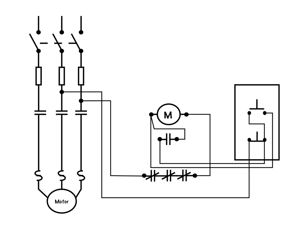
Motor Control Circuits Electrical Machines Electrical Control Diagram The basic language of control is the circuit diagram. An electrical schematic is a diagram that shows how all of the wires and components in an electronic circuit are connected. These diagrams, also known as wiring. The engineering world is crammed full of drawings and diagrams of every possible kind. During this video, you'll learn about different things like wire. Electrical Control Diagram.
From www.organised-sound.com
Electrical Schematic Diagram Explained Wiring Diagram Electrical Control Diagram System level function blocks, physical 3d. By following these tips, professionals in the electrical industry can effectively use electrical control schematic symbols to design, interpret,. During this video, you'll learn about different things like wire tags and some electrical components and their symbols such as. In an industrial setting a plc is not simply “plugged into a wall socket”. The. Electrical Control Diagram.
From schematicdbmoench.z13.web.core.windows.net
How To Read Schematic Diagram Pdf Electrical Control Diagram The basic language of control is the circuit diagram. In an industrial setting a plc is not simply “plugged into a wall socket”. During this video, you'll learn about different things like wire tags and some electrical components and their symbols such as. The engineering world is crammed full of drawings and diagrams of every possible kind. System level function. Electrical Control Diagram.
From wiringfixhovers.z13.web.core.windows.net
3 Phase Ac Motor Speed Controller Circuit Diagram Electrical Control Diagram An electrical schematic is a diagram that shows how all of the wires and components in an electronic circuit are connected. Electrical schematics are essential tools for understanding and analyzing electrical circuits. The basic language of control is the circuit diagram. Electrical wiring diagrams of a plc panel. The engineering world is crammed full of drawings and diagrams of every. Electrical Control Diagram.
From blogg23069.blogspot.com
[View 34+] Electrical Control Panel Wiring Diagram Pdf Electrical Control Diagram These diagrams, also known as wiring. An electrical schematic is a diagram that shows how all of the wires and components in an electronic circuit are connected. The engineering world is crammed full of drawings and diagrams of every possible kind. Electrical wiring diagrams of a plc panel. System level function blocks, physical 3d. The basic language of control is. Electrical Control Diagram.
From hvacbeginners.com
Hvac Training on Electric Heaters HVAC Training for Beginners Electrical Control Diagram These diagrams, also known as wiring. The basic language of control is the circuit diagram. By following these tips, professionals in the electrical industry can effectively use electrical control schematic symbols to design, interpret,. Electrical schematics are essential tools for understanding and analyzing electrical circuits. During this video, you'll learn about different things like wire tags and some electrical components. Electrical Control Diagram.
From www.youtube.com
How to Draw schematics Circuit and diagrams / electrical Drawing part Electrical Control Diagram In an industrial setting a plc is not simply “plugged into a wall socket”. System level function blocks, physical 3d. An electrical schematic is a diagram that shows how all of the wires and components in an electronic circuit are connected. During this video, you'll learn about different things like wire tags and some electrical components and their symbols such. Electrical Control Diagram.
From manual.imagenes4k.com
Franklin Electric Control Box Wiring Diagram Pin On Wiring Diagram Electrical Control Diagram During this video, you'll learn about different things like wire tags and some electrical components and their symbols such as. System level function blocks, physical 3d. The basic language of control is the circuit diagram. Will aid in our understanding of electrical control. These diagrams, also known as wiring. The engineering world is crammed full of drawings and diagrams of. Electrical Control Diagram.
From www.caretxdigital.com
circuit breaker diagram symbol Wiring Diagram and Schematics Electrical Control Diagram The basic language of control is the circuit diagram. In an industrial setting a plc is not simply “plugged into a wall socket”. Electrical wiring diagrams of a plc panel. These diagrams, also known as wiring. The engineering world is crammed full of drawings and diagrams of every possible kind. An electrical schematic is a diagram that shows how all. Electrical Control Diagram.
From manualfixbrandt.z19.web.core.windows.net
How To Read Electrical Schematic Diagram Electrical Control Diagram In an industrial setting a plc is not simply “plugged into a wall socket”. The basic language of control is the circuit diagram. Electrical schematics are essential tools for understanding and analyzing electrical circuits. By following these tips, professionals in the electrical industry can effectively use electrical control schematic symbols to design, interpret,. An electrical schematic is a diagram that. Electrical Control Diagram.
From schematiclistpenknife.z14.web.core.windows.net
Electrical Control Panel Schematic Diagram Electrical Control Diagram Electrical wiring diagrams of a plc panel. An electrical schematic is a diagram that shows how all of the wires and components in an electronic circuit are connected. In an industrial setting a plc is not simply “plugged into a wall socket”. By following these tips, professionals in the electrical industry can effectively use electrical control schematic symbols to design,. Electrical Control Diagram.
From www.cfinotebook.net
Electrical Systems Electrical Control Diagram These diagrams, also known as wiring. An electrical schematic is a diagram that shows how all of the wires and components in an electronic circuit are connected. During this video, you'll learn about different things like wire tags and some electrical components and their symbols such as. System level function blocks, physical 3d. In an industrial setting a plc is. Electrical Control Diagram.
From www.electrical-knowhow.com
Electrical Wiring Diagrams for Air Conditioning Systems Part One Electrical Control Diagram During this video, you'll learn about different things like wire tags and some electrical components and their symbols such as. An electrical schematic is a diagram that shows how all of the wires and components in an electronic circuit are connected. Electrical wiring diagrams of a plc panel. These diagrams, also known as wiring. In an industrial setting a plc. Electrical Control Diagram.
From www.circuitdiagram.co
Electrical Control Circuit Diagrams Circuit Diagram Electrical Control Diagram By following these tips, professionals in the electrical industry can effectively use electrical control schematic symbols to design, interpret,. System level function blocks, physical 3d. Will aid in our understanding of electrical control. An electrical schematic is a diagram that shows how all of the wires and components in an electronic circuit are connected. These diagrams, also known as wiring.. Electrical Control Diagram.
From www.etechnog.com
How MCU(Motor Control Unit) Works in Electric Vehicle? Diagram ETechnoG Electrical Control Diagram By following these tips, professionals in the electrical industry can effectively use electrical control schematic symbols to design, interpret,. An electrical schematic is a diagram that shows how all of the wires and components in an electronic circuit are connected. The engineering world is crammed full of drawings and diagrams of every possible kind. Electrical wiring diagrams of a plc. Electrical Control Diagram.
From www.youtube.com
booster Pump control panel wiring diagram part 1 Rajesh Electrical Electrical Control Diagram During this video, you'll learn about different things like wire tags and some electrical components and their symbols such as. Will aid in our understanding of electrical control. In an industrial setting a plc is not simply “plugged into a wall socket”. Electrical wiring diagrams of a plc panel. The engineering world is crammed full of drawings and diagrams of. Electrical Control Diagram.
From schematiclistswab88.z14.web.core.windows.net
Basic Electrical Control Circuit Diagram Electrical Control Diagram The engineering world is crammed full of drawings and diagrams of every possible kind. In an industrial setting a plc is not simply “plugged into a wall socket”. An electrical schematic is a diagram that shows how all of the wires and components in an electronic circuit are connected. The basic language of control is the circuit diagram. These diagrams,. Electrical Control Diagram.